Industrial designers often face a fundamental conflict: a sleek, minimalist aesthetic fights against the physical necessity of heat dissipation. The solution isn’t to compromise on design, but to treat thermal management as an integral part of the design process from day one. By understanding the physics of heat flow, we can transform the device’s own structure into an efficient, silent cooling system, ensuring both beauty and sustained performance.
As an industrial designer, you’re tasked with creating objects of desire. The goal is a product that feels impossibly thin, seamless, and powerful. Yet, as a thermal engineer, I know that every millimeter you shave off, every vent you remove in the name of a clean line, adds to a “thermal budget” we must somehow balance. The common approach is to treat cooling as an afterthought—something to be solved with a fan or a last-minute heat sink crammed into a leftover corner. This inevitably leads to compromises: the device gets too hot, the fan is too loud, or worse, performance degrades silently after just a few minutes of use.
The central conflict is that the very things that define a premium aesthetic—tight tolerances, sealed enclosures, and powerful processors in a small footprint—are the perfect ingredients for a thermal disaster. But what if we reframe the problem? Instead of viewing the enclosure as a prison for heat, what if we see it as the primary tool for its dissipation? This requires moving beyond the superficial debate of “vents or no vents” and embracing a deeper, physics-based approach to design.
This guide abandons the idea of thermal management as a late-stage fix. Instead, it presents it as a core design discipline. We will explore how to architect heat flow intelligently, turning constraints into opportunities. We’ll analyze how to leverage a device’s chassis for cooling, understand the real-world impact of component placement, and use modern prototyping to validate these concepts long before production.
This article provides a thermal engineer’s perspective on integrating heat management directly into the aesthetic design process. Explore the key principles and trade-offs required to build products that are both beautiful and functionally excellent.
Summary: How to Design Consumer Electronics That Look Premium Without Overheating?
- Why does trapping heat in a plastic enclosure degrade component life by 50%?
- How to use the aluminum chassis to dissipate heat without burning the user’s hands?
- Fan or Vents: Which cooling solution ruins the aesthetic line less?
- The invisible design flaw that slows down the processor after 10 minutes of use
- Where to position the battery relative to the CPU to prevent hot spots?
- Why do solar lights dim by 50% when the battery gets cold?
- Why do natural fibers prevent mold better than synthetic foam in old stone walls?
- How to Orient 3D Models to Prevent Print Failures and Weak Spots?
Why does trapping heat in a plastic enclosure degrade component life by 50%?
The primary reason plastic enclosures become thermal traps is their inherently low thermal conductivity. Unlike metals, most standard plastics are excellent insulators, meaning heat generated by components like the CPU or power regulators has nowhere to go. This trapped heat causes a rapid rise in the internal ambient temperature. The core of the problem lies in solid-state physics and chemical degradation, a relationship quantified by the Arrhenius equation. In practical terms, this means that for every 10°C increase in operating temperature, the component’s lifespan is halved. This is not a slow, linear decline; it’s an exponential acceleration of failure.
A processor designed to last 10 years at 75°C might only last five years at 85°C, and just two and a half at 95°C. This degradation manifests in various ways, from electrolyte evaporation in capacitors to electromigration in semiconductor junctions. For the user, this translates to a device that becomes unreliable or fails completely long before its expected end-of-life. Therefore, managing the Thermal Design Power (TDP)—the maximum heat a system can dissipate—isn’t just about performance; it’s a fundamental requirement for product reliability. A premium product that fails prematurely is a contradiction in terms.
To combat this, thermal management must be considered from the initial concept. This means moving away from standard plastics or designing ways for them to conduct heat. Options include using thermally conductive plastics, which are filled with materials like graphite or ceramic. These materials offer a compromise, providing better heat transfer than standard polymers while retaining the design flexibility and lower cost of plastic molding. Another strategy for sealed devices is to meticulously design the internal architecture to promote natural convection, using ribs and channels to guide even the slightest internal air movement toward cooler surfaces.
How to use the aluminum chassis to dissipate heat without burning the user’s hands?
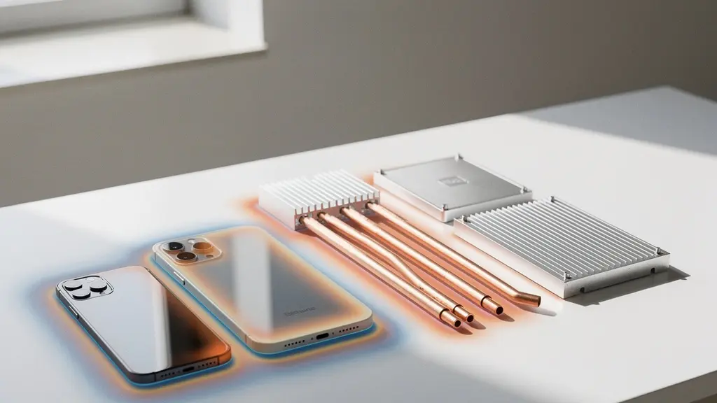
An aluminum chassis is a powerful tool in our thermal budget, but using it effectively is a balancing act. Aluminum is an excellent conductor, which is both a benefit and a risk. The goal is not just to move heat *out* of the core components, but to move it to specific, non-critical areas of the enclosure where it can dissipate to the environment without causing user discomfort. A surface temperature above 45°C can feel uncomfortably hot, and anything approaching 60°C can cause low-temperature burns with prolonged contact. The key is to create a deliberate thermal gradient across the device’s surface.
This is achieved by intelligently coupling heat-generating components (like the CPU) to the chassis using thermal interface materials (TIMs) like graphite sheets or heat pipes. These elements act as heat highways, directing thermal energy away from the source and spreading it over a much larger surface area. By increasing the area of dissipation, we lower the peak temperature at any single point. The art lies in directing this heat flow to parts of the device the user is unlikely to touch during operation—for example, the underside of a laptop or the top edge of a tablet when held in landscape mode.
As this visualization of thermal zoning suggests, a successful design establishes distinct hot and cool zones. The areas intended for user contact must be thermally “decoupled” or isolated from the main heat path. This can be achieved by using materials with different finishes, as a polished surface dissipates heat differently than a bead-blasted one, or by creating micro-gaps in the internal structure to act as thermal breaks. Computational Fluid Dynamics (CFD) simulation is essential here to map out these surface temperatures under various use cases long before a physical prototype is made, ensuring the final product is safe and comfortable to hold.
Fan or Vents: Which cooling solution ruins the aesthetic line less?
The debate between active cooling (fans) and passive cooling (vents) is often framed as a simple aesthetic choice, but this oversimplifies the engineering reality. From a purely minimalist design perspective, a sealed, fanless enclosure is the ideal. However, for any device with a significant thermal budget, this is often physically impossible. Vents are the next logical step, but their placement and design can disrupt clean surfaces. A fan introduces even more complexity: it requires internal volume, creates noise, and represents another potential point of failure. The decision, however, shouldn’t be about aesthetics alone.
The more nuanced question is about performance consistency and user experience. A fan allows a device to sustain its peak performance indefinitely by actively forcing convection. A fanless design, by contrast, might offer a high “sprint” performance but will quickly need to throttle down for “marathon” tasks. The true compromise lies in the user’s perception. As thermal management expert Tom Gregory notes, the conversation is evolving:
It’s not ‘fan vs. no fan,’ but ‘silent vs. audible.’ The psychoacoustics of fan noise matter more than the presence of the fan itself.
– Tom Gregory, Electronic Design interview on thermal management
This concept of psychoacoustics is critical. A low-volume fan that produces a steady, low-frequency hum is far less intrusive than a tiny, high-speed fan that emits a high-pitched whine, even if the latter is technically “quieter” in decibels. The design challenge then becomes about noise quality, not just presence. This can be addressed by using larger, slower-spinning fans, designing smoother airflow paths to prevent turbulence, and using simulation to optimize fan performance. For example, CFD simulations can rapidly test different fan inlet flow rates to find the optimal balance between cooling performance and audible noise, validating a design in hours instead of weeks of physical prototyping.
The invisible design flaw that slows down the processor after 10 minutes of use
Thermal throttling is the silent killer of user experience. It’s an emergency self-preservation mechanism where a processor intentionally reduces its clock speed (and thus its performance) to avoid overheating and permanent damage. For the user, the symptom is a device that feels snappy for the first few minutes but then becomes sluggish, laggy, or unresponsive during sustained tasks like gaming, video editing, or even a long video call. This isn’t a bug; it’s a design failure. It signifies that the device’s thermal system is incapable of handling the processor’s heat output under real-world load, forcing the software to intervene.
This flaw is “invisible” because the device doesn’t crash or display an error message. It simply gets slower. The root cause is a mismatch between the processor’s TDP and the enclosure’s ability to dissipate that heat. This often happens when a powerful chip is placed in a very thin, sealed enclosure with insufficient thermal mass. Thermal mass refers to a material’s ability to absorb heat, acting as a temporary buffer. A design with low thermal mass will see its temperature spike almost instantly, triggering throttling immediately. A design with higher thermal mass (e.g., using thicker copper heat spreaders or vapor chambers) can absorb the initial burst of heat, delaying the onset of throttling and providing a better “sprint” performance.
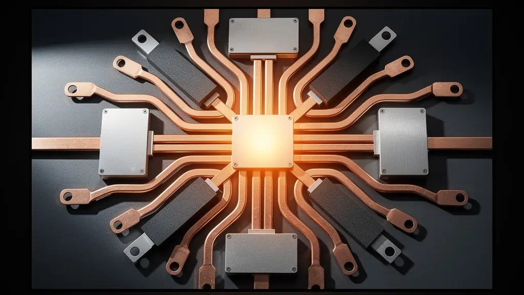
As shown in this visualization of a thermal stack, preventing throttling requires a multi-layered approach. Heat must be efficiently pulled away from the processor die itself and spread across a wider area. Advanced materials like graphite sheets and vapor chambers are crucial tools for this. The ultimate goal is to achieve Performance Consistency, where the device can operate at a predictable performance level for extended periods. As thermal simulation studies demonstrate that reducing temperature by 10 degrees can double component expected life, avoiding throttling not only improves user experience but also drastically increases product reliability.
Action Plan: Preventing Thermal Throttling by Design
- Early Analysis: Start thermal analysis in the product roadmap from the very beginning of the concept phase, not after the industrial design is locked.
- Accurate Calculation: Calculate thermal systems accurately using CFD software like Ansys Icepak or 6SigmaET to predict heat flow and hot spots.
- Performance Profiling: Design for ‘Performance Consistency’ with predictable ‘sprint’ (short burst) and ‘marathon’ (sustained) power profiles.
- Advanced Spreaders: Leverage advanced heat spreaders like graphite sheets and vapor chambers to increase the system’s overall thermal mass.
- Co-Design: Implement System-on-Chip (SoC) package co-design with chip manufacturers to prevent localized hot spots at the source.
Where to position the battery relative to the CPU to prevent hot spots?
Component layout is a three-dimensional puzzle with significant thermal consequences. The most critical relationship in modern electronics is between the main processor (CPU/SoC) and the battery. Placing these two components close together is a recipe for disaster. The CPU is typically the primary heat source, while the battery is extremely sensitive to temperature. Exposing a lithium-ion battery to excessive heat (generally above 45°C) not only accelerates its degradation and permanently reduces its capacity but also poses a serious safety risk, potentially leading to thermal runaway.
The guiding principle is thermal isolation. Ideally, the CPU and battery should be placed on opposite ends of the device’s mainboard or even in separate physical compartments. If space constraints force them to be in closer proximity, a dedicated thermal barrier is non-negotiable. This could be an air gap, which is a surprisingly effective insulator, or a layer of specialized insulation material like aerogel. Furthermore, any heat spreading solution (like a heat pipe or vapor chamber) connected to the CPU must be routed well away from the battery. Directing a heat pipe over the battery is equivalent to building a dedicated heater for the component you most need to keep cool.
The challenge is amplified in ultra-thin devices where every cubic millimeter is contested. This is where simulation becomes indispensable. Engineers use tools for Computational Fluid Dynamics (CFD) and Finite Element Analysis (FEA) to model the complete thermal system. These simulations allow designers to visualize temperature distribution and heat flow from the CPU, identifying potential hot spots on the battery long before a physical prototype exists. This data-driven approach allows for the optimization of component placement and the design of targeted cooling strategies, ensuring both performance and safety are addressed from the earliest design stages.
Why do solar lights dim by 50% when the battery gets cold?
While our focus is often on dissipating excess heat, a truly premium device must perform flawlessly across its entire operational environment. This brings us to a challenge common in outdoor electronics, which serves as an important lesson: cold-weather performance. A solar light dims in the cold for the same reason a high-end smartphone might shut down unexpectedly on a ski slope: battery chemistry is highly dependent on temperature. The electrochemical reactions that allow a battery to discharge (provide power) slow down dramatically as temperatures drop. This increases the battery’s internal resistance, reducing its ability to deliver current.
Most thermal management research indicates that nominal battery performance is specified for a +20°C to +30°C range. Below freezing, a battery’s available capacity can be effectively halved, even if it is fully charged. This is not permanent damage, but a temporary reduction in performance. For a solar light, it means dim output; for a premium electronic device, it could mean sluggish operation or an emergency shutdown to protect the battery. Designing for this “full environmental spectrum” is a mark of superior engineering.
Solutions are often inspired by other industries, like automotive, which have long dealt with extreme temperatures. Small, low-power battery pre-heaters can be integrated to keep the battery within its optimal “Goldilocks Zone.” Another advanced approach is the use of Phase-Change Materials (PCMs). These materials absorb heat when the device is warm (acting as a heat sink) and then release that stored heat when the environment gets cold, passively stabilizing the battery’s temperature. The choice of battery chemistry itself is also a factor, with types like LiFePO4 offering a wider operational temperature range than standard Li-ion. This holistic view—designing for both extreme heat and cold—is what separates a good product from a great one.
Why do natural fibers prevent mold better than synthetic foam in old stone walls?
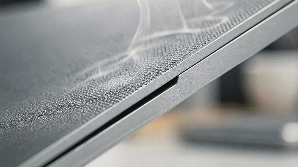
This question, seemingly from the world of architecture, holds a surprisingly relevant lesson for industrial design: the choice of material impacts more than just look and feel. In electronics, we are constantly exploring new materials to enhance the user’s tactile experience and convey a sense of premium quality. While aluminum and glass dominate, designers are increasingly experimenting with wood, leather, and advanced fabrics. These “natural” or unconventional materials bring a unique warmth and texture, but they also present unique thermal challenges. A wood veneer, for instance, is an even better insulator than plastic.
The challenge is to incorporate these materials without sacrificing thermal performance. This requires clever engineering. For example, a device with a wooden back might use an internal aluminum sub-frame as the primary heat spreader, with the wood acting purely as an aesthetic, non-structural skin. The gap between the sub-frame and the wood can be engineered to create an airflow channel. In this context, specialized materials like silicone become critical. It is increasingly used not for the external chassis, but for internal Thermal Interface Materials (TIMs). These custom silicone formulations can provide excellent heat transfer between a processor and a heat sink while also offering vibration damping and electrical insulation.
This approach allows designers to achieve the best of both worlds: the external material is chosen for its aesthetic and tactile qualities, while the internal architecture and hidden materials do the heavy lifting of thermal management. It’s about creating a holistic system where every material has a specific job. Just as natural fibers in a wall manage moisture in a way synthetics can’t, our choice of internal materials must be precisely tailored to manage heat in ways the external “showcase” materials cannot. This separation of duties is key to enabling more creative and diverse material choices in premium electronics.
Key Takeaways
- Heat as a Budget: Treat the amount of heat a device can dissipate as a finite “thermal budget” that must be managed from the first design sketch.
- Chassis as a Tool: Intelligently use the device’s own structure, particularly metal chassis, as the primary heat sink, directing heat to non-contact areas.
- Performance Consistency Over Peak Speed: Design to avoid thermal throttling, ensuring the user experiences smooth, reliable performance over extended periods, not just for the first five minutes.
How to Orient 3D Models to Prevent Print Failures and Weak Spots?
While this question is core to 3D printing, its relevance for us is in rapid thermal prototyping. Before committing to expensive injection molding tools or CNC machining, we need to test our thermal theories quickly and cheaply. 3D printing allows us to create physical mockups of our enclosures to test fit, form, and, crucially, thermal performance. The orientation of the print is critical here. Fused Deposition Modeling (FDM) prints exhibit anisotropic properties, meaning they conduct heat differently depending on the direction of the printed layers. Heat transfers more effectively *across* layers than *along* them.
Therefore, when printing a prototype enclosure for a thermal test, the model must be oriented so that the layer lines do not impede the intended heat flow path. We can even use specialized, thermally-conductive filaments filled with graphite or carbon fiber to create prototypes that more closely mimic the behavior of a final production part. This allows for early, tangible validation of our CFD simulations. For even higher fidelity, we can create “thermal dummies”—blocks of CNC-milled aluminum fitted with cartridge heaters set to the processor’s TDP. By placing these inside a prototype enclosure, we can use thermal cameras to measure actual surface temperatures and compare them directly to our simulation data.
This iterative cycle of simulation, rapid prototyping, and physical testing is the key to de-risking a design. It allows the engineering and design teams to identify flaws and optimize the thermal architecture when changes are still cheap and easy to make. As generative design tools become more powerful, this process is becoming even more streamlined. For instance, recent developments have shown that a generatively designed copper heatsink can achieve a +60% heat transfer efficiency compared to a conventionally designed one, all while optimizing for weight and space. This fusion of simulation and rapid prototyping is the future of high-performance product development.
By integrating thermal management as a foundational element of industrial design, we move beyond the frustrating cycle of compromise. Instead of fighting against physics, we can leverage it, creating devices that are not only beautiful and sleek but also cool, reliable, and consistently performant. The next step is to apply these principles to your own design process, starting with the earliest concept sketches.