In summary:
- Part strength is anisotropic; orient models so that critical forces travel along the length of printed layers, not across them.
- Structural integrity comes more from wall thickness (perimeters) than high infill percentages. Add walls before adding infill.
- Strategic orientation minimizes the need for supports, improves surface finish, and manages thermal stress for cleaner overhangs.
- Anticipating manufacturing needs, like draft angles for molding, during the 3D printing stage saves significant time and cost later.
Every maker knows the frustration: a multi-hour print finishes, only for the part to snap cleanly along its layer lines with minimal force. The common advice is to simply re-orient the model to minimize supports or print it flat on the bed for stability. While sometimes helpful, this superficial approach often ignores the fundamental physics at play. It treats 3D printing as a simple act of stacking plastic, rather than what it truly is: a desktop manufacturing process governed by material science and structural mechanics.
The truth is, a part’s orientation is the single most important decision you make before hitting “print.” It dictates not only the final strength and durability but also the surface quality, printing time, and material consumption. Failing to consider the underlying principles is like building a house without understanding which walls are load-bearing. The structure is destined to be weak, unreliable, and prone to failure precisely where you need it to be strong.
This guide moves beyond the basics. We will explore orientation from a structural engineering perspective. Instead of offering simple rules of thumb, we will delve into the *why* behind the failures. You’ll learn to think about concepts like anisotropy, thermal stress management, and load paths. By understanding these core principles, you can transform your approach from one of guesswork to one of intentional design, producing parts that are not just visually accurate but mechanically robust and truly functional.
This article provides a structured approach to mastering part orientation. We will cover everything from the fundamental weakness of layer adhesion to advanced strategies for thermal management and designing for future manufacturing processes like injection molding.
Summary: A Structural Guide to 3D Print Orientation
- Why printing a vertical rod makes it 5x weaker than printing it horizontally?
- Tree Supports vs. Standard Supports: Which saves material without scarring the surface?
- The cooling mistake that causes your overhangs to droop and ruin the shape
- How much infill do you really need for a functional bracket?
- How to post-process PLA prints to hide layer lines without losing detail?
- How to adjust your 3D model angles so it can actually pop out of a steel mold?
- Why does trapping heat in a plastic enclosure degrade component life by 50%?
- Moving from 3D Print to Injection Molding: When Is the Investment Justified?
Why Printing a Vertical Rod Makes It 5x Weaker Than Printing It Horizontally?
The core reason for this dramatic strength difference lies in a single, critical concept: anisotropy. In FDM 3D printing, a part’s mechanical properties are not uniform in all directions. A horizontally printed rod has continuous strands of filament running its entire length, making it incredibly strong under tension, much like a bundle of fibers. However, when you print the same rod vertically, its strength relies entirely on the chemical bonds between each successive layer. These bonds, formed as hot plastic is laid on top of slightly cooled plastic, are inherently weaker than the polymer itself.
This creates a plane of weakness across every single layer. When force is applied perpendicular to these layers (e.g., trying to bend or pull apart a vertical rod), the part will fail at this weakest link—the layer-to-layer adhesion. This is not a minor difference; it’s a fundamental structural flaw. As experts at CNC Kitchen have extensively tested, the adhesion between layers is the primary bottleneck for part strength in extrusion-based printing.
This results is one of the biggest problems of extrusion-based 3D printing, which is the significantly lower strength perpendicular to layers compared to in the printing plane. Layers that are stacked on top of each other only partly melt together, creating a weak point, and if these weak points are all in one plane, this is where a part will fail.
– CNC Kitchen, Layer Adhesion Analysis
Therefore, the golden rule of orientation for strength is to analyze the expected load paths. If a part will be pulled, bent, or twisted, you must orient it so the forces travel along the length of the continuous filament paths, not across the weak layer lines. For a simple hook, this means printing it on its side, not standing up, ensuring the main stress is handled by the filament’s intrinsic tensile strength.
Tree Supports vs. Standard Supports: Which Saves Material Without Scarring the Surface?
The choice between support types is a critical decision in the orientation process, balancing material use, print time, and final surface quality. While standard (linear or grid) supports are predictable and effective for large, flat overhangs, they often act as a blunt instrument. They create significant contact area with the model, leading to surface scarring upon removal and consuming a large amount of filament. Tree supports, on the other hand, offer a more elegant, organic solution, particularly for complex and irregular models.
Generated by algorithms that mimic the branching growth of trees, these supports start from a few points on the build plate and reach upwards, touching the model only at the most necessary points. This minimalistic approach is highly efficient; depending on the model’s geometry, tree supports can lead to 20-40% less filament usage compared to their standard counterparts. This not only saves money but also significantly reduces print time and waste.

The most significant advantage for many makers, however, is the vastly improved surface quality. Because the branches of tree supports terminate in fine points, the contact area with the model is minimal. This means fewer “witness marks” or scars are left on the final part, drastically reducing the need for post-processing like sanding or filling. This is especially crucial for organic shapes, miniatures, and artistic models where surface finish is paramount.
This table from a comparative analysis of support types provides a clear guide for when to use each approach.
| Model Type | Recommended Support | Material Savings | Surface Quality |
|---|---|---|---|
| Organic shapes/Miniatures | Tree Supports | 25-50% less | Minimal scarring |
| Large flat overhangs | Standard Supports | Standard usage | Some marking |
| Complex internal geometries | Tree Supports | 30-40% less | Better preservation |
| Mechanical precision parts | Standard Supports | Standard usage | Predictable contact |
The Cooling Mistake That Causes Your Overhangs to Droop and Ruin the Shape
Proper cooling is a delicate balancing act. Too little, and your overhangs become a mess of drooping, warped plastic. Too much, and you risk poor layer adhesion and brittle parts, especially with materials like ABS. The most common mistake isn’t just about fan speed; it’s about failing to account for thermal stress management through strategic orientation. The part cooling fan on most printers blows from a fixed direction, creating a “wind shadow” on the opposite side of the model. Features printed within this shadow don’t receive adequate airflow, causing them to stay molten for too long and sag under gravity.
This is why a 45-degree overhang might print perfectly on one side of your model but fail catastrophically on the other. The successful side was facing the fan, allowing the filament to solidify almost instantly after extrusion. The failing side was in the wind shadow, remaining soft and unable to support itself. The solution is to orient your part with this airflow in mind. Identify the most critical or delicate overhangs and position them to face the cooling duct directly. For models with complex features on all sides, a dual-fan setup or a 360-degree fan shroud can provide more even cooling and mitigate this effect.
Material choice also dictates the cooling strategy. PLA benefits from 100% fan speed to achieve sharp details and steep overhangs. However, materials like ABS and PETG require much less cooling (often 0-30% fan speed) because they are prone to warping and delamination if they cool too quickly. For small parts with short layer times, the heat doesn’t have time to dissipate. Use your slicer’s “Minimum Layer Time” setting (e.g., 10-15 seconds) to force the print head to slow down or move away, allowing each layer to solidify before the next is applied. This prevents the nozzle from remelting the layers below and turning small features into a molten blob.
How Much Infill Do You Really Need for a Functional Bracket?
A common misconception among makers is that a stronger part requires a higher infill percentage. While increasing infill from 10% to 50% will certainly add strength, it’s an inefficient way to achieve structural integrity and drastically increases print time and material cost. The secret to strong, functional parts like brackets lies not in the density of the infill, but in the thickness of the walls, or perimeters. The outer shells of a print bear the vast majority of the torsional and bending loads.
From an engineering perspective, this makes perfect sense. An I-beam gets its strength from its wide top and bottom flanges (the “walls”), not the thin web in the middle (the “infill”). The same principle applies here. In fact, research shows that increasing wall count provides significantly more strength per gram of plastic than increasing infill. For most functional brackets, starting with 3-4 perimeters and a modest 20-30% infill is a far more effective strategy than using 2 perimeters with 80% infill.
To further optimize, think strategically about where the stress is concentrated. A bracket doesn’t need to be uniformly dense. Use slicer features like “modifier meshes” or “variable infill” to apply 100% infill only around high-stress areas like screw holes or sharp corners, while keeping the rest of the part at a lower, more efficient density. The infill pattern also matters: gyroid is excellent for omnidirectional strength and shock absorption, while grid or rectilinear patterns are best for parts loaded along the X/Y axes. This targeted approach creates a part that is both strong and lightweight—the definition of structural efficiency.
How to Post-Process PLA Prints to Hide Layer Lines Without Losing Detail?
Achieving a perfectly smooth, injection-molded look on an FDM print is a common goal, but traditional methods like sanding are labor-intensive and often destroy fine surface details. While post-processing can work wonders, the most effective strategy begins before you even print: orientation for surface quality. Aesthetically critical surfaces should be oriented vertically (along the Z-axis) whenever possible. This leverages the high resolution of the X/Y axes to produce the smoothest possible finish on those faces. Conversely, surfaces oriented parallel to the build plate (top and bottom layers) will show more pronounced stepping, known as the “stair-stepping effect,” especially on gentle curves.
Slicer settings can also dramatically reduce the need for post-processing. Placing the Z-seam—the point where the printer starts and ends each outer layer—on a sharp corner or a hidden part of the model can make it virtually invisible. Furthermore, using a “variable layer height” feature allows you to print visible, curved sections at a high resolution (e.g., 0.1mm) and flat, hidden sections at a lower resolution (e.g., 0.3mm), saving time without sacrificing appearance. For perfectly smooth top surfaces, the “Ironing” feature, where the hot nozzle makes a final pass over the top layer to melt it smooth, is invaluable.
Case Study: UV Resin Coating for Detail Preservation
When mechanical methods are not an option, chemical smoothing offers a powerful alternative. For materials like ABS, acetone vapor smoothing is effective but can soften sharp details. For PLA, a superior method is to apply a thin coat of self-leveling epoxy or UV-curable resin. Artists and model makers report exceptional results with products like XTC-3D, which fills in the microscopic valleys of layer lines without pooling in and obscuring fine textures. This method can help maintain up to 95% of the original model’s detail while producing a glass-smooth, paintable surface, making it ideal for miniatures and display pieces.
By combining smart orientation with strategic slicer settings and, when needed, a light-touch chemical process, you can achieve surfaces that rival those from far more expensive manufacturing methods. The key is to think about the final finish from the very beginning of the process.
How to Adjust Your 3D Model Angles so It Can Actually Pop Out of a Steel Mold?
Moving from a 3D printed prototype to an injection-molded part requires a fundamental shift in design thinking. While a 3D printer can create almost any geometry, including overhangs and internal voids, an injection mold is a rigid two-part (or more) tool. For a part to be manufacturable, it must be able to be ejected cleanly from the mold cavity without getting stuck. This is where the concept of a draft angle becomes non-negotiable. A draft angle is a slight taper, typically 1-3 degrees, applied to all walls that are parallel to the direction the mold opens and closes (the “pull direction”). Without this taper, the friction between the part’s vertical walls and the steel mold creates a vacuum, making ejection impossible without damaging the part or the mold.
Another critical consideration is eliminating undercuts. An undercut is any feature that would prevent the part from being pulled directly out of the mold half. A simple L-shaped bracket, for example, has a massive undercut. 3D printing handles this with ease, but in molding, it would require a complex and expensive mechanism called a side-action or slide. The goal when designing for molding is to simplify geometry and establish a clear “parting line” where the two halves of the mold will meet, ensuring there are no features that hook or catch during ejection.
Case Study: 3D Printing as a Mold Simulation Tool
Engineers cleverly use FDM printing to pre-validate their designs for molding. By orienting their part in the 3D printer in the exact same direction it will be pulled from the mold, they can run a simple test: if the part requires supports to print successfully in that orientation, it has undercuts that will cause problems in injection molding. This simple, inexpensive simulation allows them to identify and eliminate costly design flaws before ever committing thousands of dollars to steel tooling.
Before investing in expensive tooling, it’s crucial to ensure your design is mold-ready. The following checklist outlines the essential modifications needed to transition a 3D model for injection molding.
Action Plan: Molding-Ready 3D Model Checklist
- Add 1-3 degree draft angles to all vertical walls relative to the pull direction.
- Check for undercuts by orienting the part in its intended pull direction; any area requiring supports is an undercut.
- Eliminate all 90-degree corners on interior and exterior edges, replacing them with generous radii or chamfers to improve flow and reduce stress.
- Simplify the overall geometry to create a clear, straight-as-possible parting line definition.
- Use a 3D printer to create test parts and even simple molds (in a durable material) to validate the design and pull direction before investing in steel.
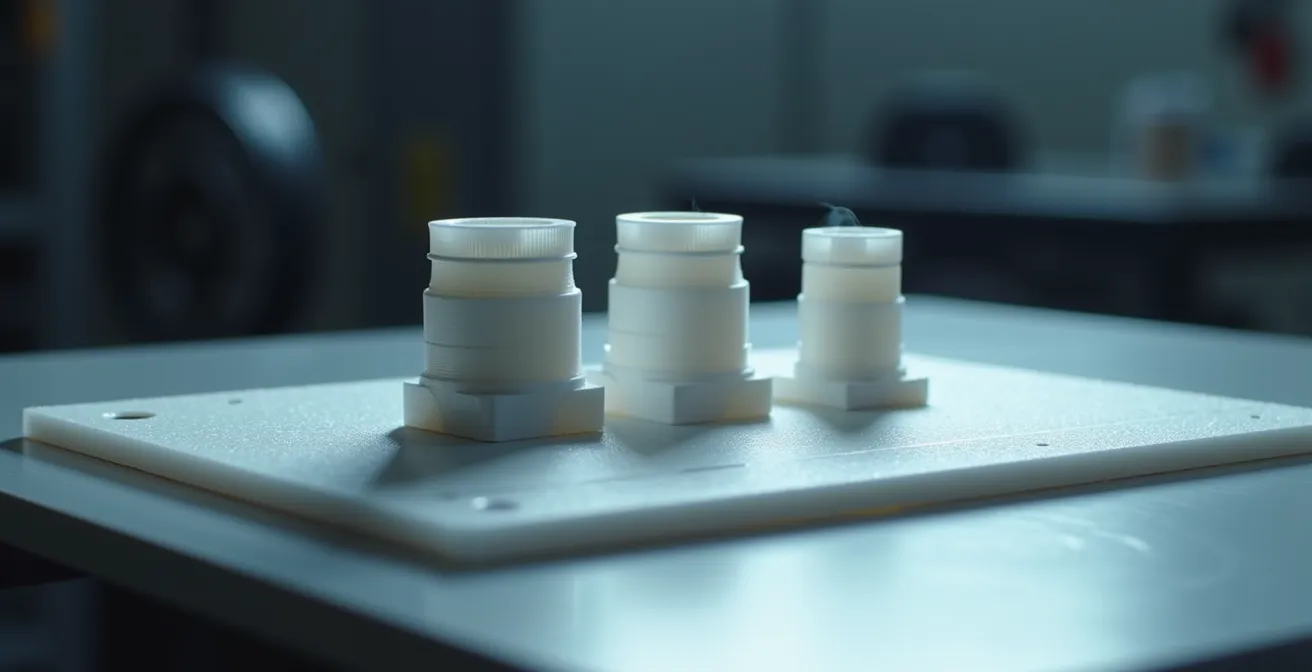
Why Does Trapping Heat in a Plastic Enclosure Degrade Component Life by 50%?
When designing an enclosure for electronics, it’s easy to focus solely on the fit and form, forgetting that the enclosure itself becomes a critical part of the system’s thermal management. Trapping heat-generating components inside a sealed plastic box is a recipe for disaster. Every electronic component has an optimal operating temperature range, and exceeding it dramatically shortens its lifespan and can lead to premature failure. The plastic itself is also vulnerable; as material selection data shows that PLA deforms at 60°C, a temperature easily reached inside a poorly ventilated case housing a processor or power regulator. Materials like ABS or ASA offer higher temperature resistance but can’t solve the core problem of trapped heat.
The solution lies in passive thermal management designed directly into the 3D model. This means thinking about airflow from the very beginning. Hot air rises, so the most effective ventilation strategy involves creating intake vents near the bottom of the enclosure and exhaust vents near the top. This encourages a natural convection cycle, allowing cool air to be drawn in while hot air escapes. The orientation of these vents is critical; vertical slots are far more effective at promoting this chimney-like airflow than horizontal ones.
The internal structure of the print can also contribute to cooling. Using an open-cell infill pattern like Gyroid or Cubic, rather than a dense grid, allows air to circulate within the walls of the enclosure, helping to dissipate heat more effectively across the entire surface. For testing purposes, printing a prototype in a transparent material like PETG allows you to use smoke or a thermal camera to visualize airflow patterns and identify “hot spots” where air is stagnating. By integrating these passive cooling strategies into your orientation and design choices, you transform the enclosure from a simple box into an active part of the thermal solution, ensuring the longevity and reliability of the components within.
Key Takeaways
- Strength is anisotropic; the orientation of a part relative to its expected load is the primary factor in its durability.
- Structural efficiency is key: perimeters and strategic infill provide more strength per gram of material than high-density infill alone.
- Orientation directly impacts cooling, support requirements, and surface finish, determining both the look and function of the final part.
- Thinking like a manufacturing engineer—considering draft angles and parting lines early—streamlines the transition from prototype to production.
Moving from 3D Print to Injection Molding: When Is the Investment Justified?
The journey from a single 3D printed prototype to mass production involves navigating a series of manufacturing methods, each with its own cost structure and ideal volume range. While 3D printing is unparalleled for one-off parts and initial design validation due to its zero tooling cost, its high per-unit cost makes it uneconomical for larger quantities. The decision of when to move to the next stage, such as urethane casting or full-scale injection molding, is a critical financial calculation. The primary driver is the break-even point, where the high upfront cost of creating a mold is offset by a drastically lower cost per part.
For very low volumes (1-100 units), a middle ground like silicone molding and urethane casting can be an excellent step. It requires a relatively inexpensive “master” pattern (often a perfectly finished 3D print) to create a flexible mold that can produce a few dozen high-quality copies. This is perfect for small batch runs or market testing. The true leap comes when considering injection molding, which involves machining a precise mold from aluminum or steel. While aluminum tooling is cheaper and faster to produce, it’s less durable and suitable for volumes up to around 5,000 units. For true mass production (5,000+ units), hardened steel molds are the standard, offering the lowest possible per-unit cost but requiring a significant initial investment that can run into tens of thousands of dollars.
Case Study: 3D Printing as a Financial Risk Mitigation Tool
The real value of mastering 3D print orientation and design for manufacturability is financial risk mitigation. Companies report that every significant design flaw—such as a missing draft angle or an un-moldable undercut—discovered and fixed with a $5 3D print saves an average of $3,000-$5,000 in costly and time-consuming mold modifications. Diligent prototyping doesn’t just validate a design; it de-risks a massive capital investment.
The following table, based on an industry break-even analysis, provides a general guideline for choosing the right manufacturing method based on your required production volume.
| Production Volume | Recommended Method | Unit Cost | Tooling Cost |
|---|---|---|---|
| 1-20 units | 3D Printing (FDM/SLA) | $5-50 | $0 |
| 20-100 units | Silicone/Urethane Casting | $3-20 | $200-500 |
| 500-5000 units | Aluminum Tooling | $1-5 | $2000-5000 |
| 5000+ units | Steel Injection Mold | $0.10-1 | $10,000+ |
Apply these structural principles to your next project and start printing parts that are not just prototypes, but truly functional components.