The decision to invest in injection molding is governed less by pure volume and more by committing to a series of irreversible engineering and design principles.
- The financial breakeven point is a function of part complexity and material choice, often falling between 1,000 and 1,500 units for simple parts.
- Your 3D model is not production-ready until it incorporates non-negotiable DFM (Design for Manufacturability) features like draft angles and uniform wall thickness.
Recommendation: Before seeking quotes for a mold, conduct a rigorous DFM audit of your design and use “bridge” manufacturing methods like vacuum casting to validate the market with a few hundred units.
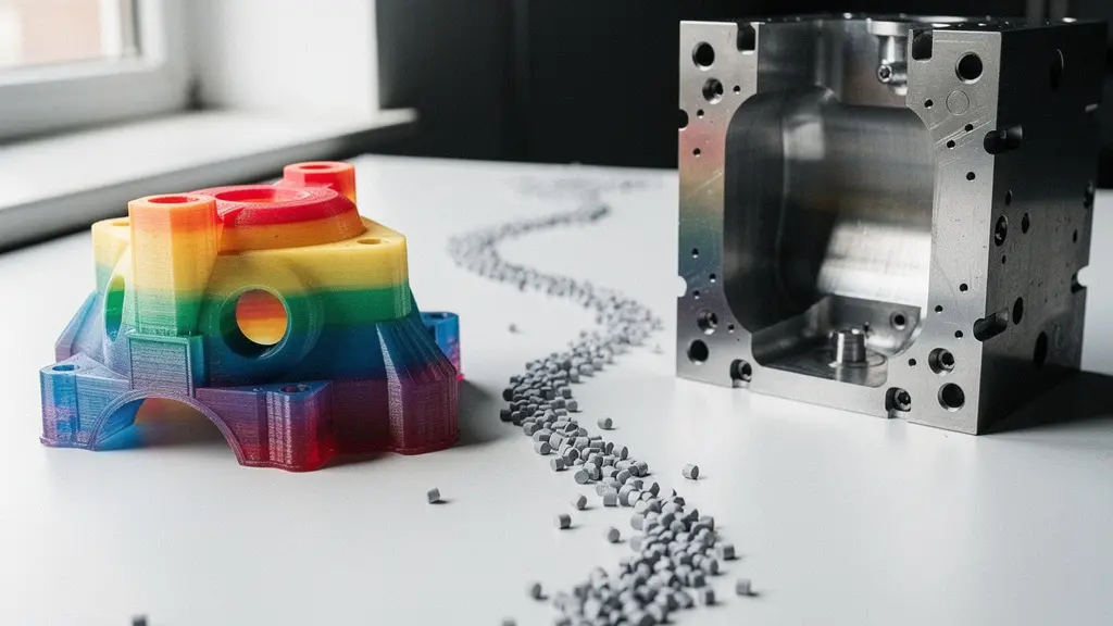
For every hardware startup, the moment arrives when the trusty office 3D printer can no longer keep up. The question of scaling production looms large, and with it, the intimidating prospect of injection molding. The initial sticker shock of a multi-thousand-dollar steel mold often paralyzes decision-making. Founders and product designers get caught in a loop, asking “Are we big enough for this?” while the costs of low-volume 3D printing continue to accumulate, eating into margins and slowing growth. This isn’t just a simple cost-per-part calculation; it’s a strategic inflection point.
Most advice simplifies the problem to a basic cost curve: 3D printing has a low setup cost but high unit cost, while injection molding is the opposite. While true, this high-level view dangerously ignores the practical, engineering-driven realities that determine success or failure. The transition isn’t just a purchase order for a tool; it’s a fundamental shift in design philosophy. A part that prints perfectly in PLA or resin will almost certainly fail in an injection mold without significant modification.
But what if the real key wasn’t just hitting a magic sales number, but rather understanding the specific, non-negotiable engineering commitments required for manufacturability? The true justification for the investment lies in mastering the trade-offs between part geometry, material science, and production timelines. This is not a leap of faith; it is a calculated engineering decision.
This guide provides a realistic, cost-focused framework for making that decision. We will dissect the financial breakeven point, detail the critical CAD model adjustments for moldability, evaluate bridge production methods for the awkward phase between 10 and 500 units, and provide a strategy for managing tooling lead times without derailing your launch.
Summary: Navigating the Transition from Prototyping to Mass Production
- Why does spending $10,000 on a mold only make sense if you sell over 1,000 units?
- How to adjust your 3D model angles so it can actually pop out of a steel mold?
- Vacuum Casting vs. CNC Machining: Which bridges the gap between 10 and 500 units?
- The shrinkage mistake that makes parts fit perfectly in PLA but fail in ABS plastic
- How to manage the 8-week lead time for tooling without delaying your launch date?
- Why a $150 ethical shirt is cheaper than a $20 fast-fashion top over 3 years?
- The cooling mistake that causes your overhangs to droop and ruin the shape
- How to Integrate Smart Fabrics into Everyday Wear Without Sacrificing Comfort?
Why does spending $10,000 on a mold only make sense if you sell over 1,000 units?
The “1,000 unit” rule is a benchmark, not a law. The actual breakeven point where the high upfront cost of an injection mold becomes more economical than 3D printing is a direct function of your part’s complexity, material, and the cost of the tool itself. The core of the calculation is simple: Total Cost = (Tooling Cost) + (Unit Volume × Price Per Part). For 3D printing, the tooling cost is zero, but the price per part is high and relatively static. For injection molding, the tooling cost is high, but the price per part plummets as volume increases.
Consider a simple plastic enclosure. 3D printing it might cost $15 per unit. An injection mold might cost $8,000, but the resulting parts are only $1.50 each. The breakeven point is where the total cost of both methods is equal. In this scenario, you’d need to sell about 590 units to justify the mold. However, if the part is more complex, requiring side-actions or intricate features, the mold cost could jump to $20,000, pushing your breakeven point well past 1,500 units.
This is not just theory. A real-world analysis for a new product illustrated this perfectly: prototype tooling at $5,675 versus single-cavity tooling at $7,665 only reached a breakeven point at 1,400 units. This cost analysis for entrepreneurs demonstrates how tooling decisions fundamentally alter unit economics. The goal isn’t just to find the breakeven point, but to understand how your design choices directly influence it. A simpler part means a simpler, cheaper mold and a faster path to profitability.
Therefore, before you can determine if the investment is justified, you must first have a design that is truly optimized for manufacturing, as this will dictate your actual tooling cost.
How to adjust your 3D model angles so it can actually pop out of a steel mold?
A 3D model designed for printing is fundamentally different from one designed for molding. The single most critical—and often overlooked—adjustment is the addition of draft angles. An injection mold is a solid block of steel. To eject a plastic part from it without it getting stuck, scraped, or broken, every vertical face must be slightly angled. Think of trying to pull a perfectly straight-sided cup out of a stack of identical cups versus a tapered one. The taper is the draft angle.
The absence of draft creates immense friction and a vacuum effect, making ejection impossible without damaging the part or the expensive mold. A minimum of 1 to 2 degrees of draft is standard for most parts on any face parallel to the direction the mold opens. If the surface has a texture (like a matte finish), this needs to be increased to 3 to 5 degrees or more to prevent the texture from being scraped off during ejection.
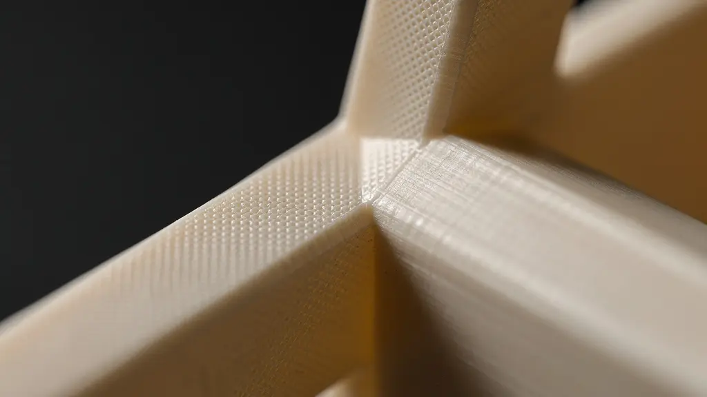
As this image highlights, draft angles are not just a technical necessity; they can be integrated as an intentional aesthetic feature, creating subtle, elegant tapered edges that catch light and enhance the product’s form. This transition from a purely additive mindset (building layer by layer) to a subtractive one (ejecting from a cavity) is the first major engineering hurdle in moving to mass production.
Action Plan: Preparing Your CAD Model for Molding
- Run parting line analysis in your CAD software to visualize where the two halves of the mold will meet and identify potential undercut issues.
- Apply a minimum of 1-3 degrees of draft to all smooth, vertical faces, increasing this to 3-5 degrees for any textured surfaces to prevent scraping.
- Core out any sections thicker than 3-4mm to maintain a uniform wall thickness, which is critical for preventing cosmetic defects like sink marks and internal voids.
- Add structural ribs to reinforce thin walls instead of making the walls thicker, ensuring the rib thickness is 50-60% of the wall it supports to avoid sink.
- Request a formal Design for Manufacturability (DFM) analysis from your chosen manufacturer before committing funds to the steel tool.
Ignoring these geometric rules is the fastest way to receive an unmanufacturable design verdict from a supplier, wasting both time and momentum.
Vacuum Casting vs. CNC Machining: Which bridges the gap between 10 and 500 units?
The chasm between a handful of 3D printed prototypes and a 1,000+ unit injection molding run is a precarious place for a startup. Committing to expensive tooling feels premature, but continuing with 3D printing is too slow and costly. This is where “bridge production” methods become critical. The two primary contenders for this phase are vacuum casting and CNC machining, each offering a distinct set of trade-offs for producing 10 to 500 units.
Vacuum casting uses a 3D printed master pattern to create a silicone mold. This flexible mold can then be used to cast around 20-50 high-fidelity parts in production-like polyurethane resins. It’s excellent for creating marketing samples, conducting beta tests, or for a first small production run. Its key strengths are speed and superb surface finish that perfectly replicates the master pattern. CNC machining, conversely, carves parts directly from a solid block of production-grade plastic or metal. This offers 100% material fidelity but can be slower and more expensive per part, and complex geometries with undercuts can be challenging.
Choosing the right method depends on your immediate priority: material accuracy or speed and surface finish. The following table breaks down the key differences, as detailed in a recent comparative analysis of bridge production methods.
| Method | Volume Range | Material Fidelity | Surface Finish | Complex Features | Lead Time |
|---|---|---|---|---|---|
| Vacuum Casting | 10-100 parts | 90% match to production | Excellent (replicates master) | Living hinges possible | 3-5 days |
| CNC Machining | 1-500 parts | 100% production material | Good (depends on tooling) | Limited undercuts | 5-10 days |
| 3D Printed Molds | 10-1000 parts | 100% production material | Good (depends on mold finish) | All features possible | 2-4 days |
Using one of these methods allows you to generate revenue, gather user feedback, and validate your market with real parts before committing six figures to hard tooling.
The shrinkage mistake that makes parts fit perfectly in PLA but fail in ABS plastic
After conquering draft angles, the next material science trap is shrinkage. Every thermoplastic shrinks as it cools from its molten state in the mold to a solid at room temperature. A part designed to be exactly 100mm long in your CAD software will not be 100mm long when it comes out of the mold. It will be smaller. This is a non-issue with most 3D printing, where thermal stresses are localized, but it’s a critical failure point in molding.
The mistake is designing for nominal dimensions. A pin and hole that fit perfectly in your PLA 3D print will either be too loose or impossible to assemble when molded in a material like ABS or Polypropylene (PP), which have different shrinkage rates. The rate is a predictable percentage unique to each material. For example, ABS shrinks by about 0.5-0.7%, while PP can shrink by as much as 1.5-2.0%. This means a 100mm part in ABS will end up being around 99.4mm.
The solution is not to manually adjust every dimension. The professional approach is to apply a material-specific scaling factor to your entire CAD model before the mold is even designed. The key is to apply a material-specific scaling factor, such as the industry-standard 1.006x for ABS, directly in your CAD model *before* creating the tool. The mold maker then machines the mold cavity to be proportionally larger, so that when the plastic part cools and shrinks, it settles at the exact intended dimensions. Forgetting this step results in parts that are out of tolerance and a final product that doesn’t assemble correctly—an extremely expensive mistake to fix after the steel has been cut.
This attention to material-specific properties separates a professional, manufacturable design from an amateur prototype.
How to manage the 8-week lead time for tooling without delaying your launch date?
The 6 to 10-week lead time for creating a steel injection mold often feels like a black hole in a product launch timeline. For a startup, this downtime can be fatal. However, savvy engineering teams don’t see this as a pause; they see it as a parallel workstream. While the heavy steel is being machined, you have a critical window of opportunity to validate your market, build hype, and even start generating revenue.
The key is to leverage the “bridge production” methods discussed earlier. Once you have finalized your design and kicked off the steel tooling process (T-8 weeks), you can immediately begin producing a run of several hundred units using 3D printed molds or vacuum casting. These parts are high-fidelity enough for marketing photoshoots, sending to influencers and reviewers, and running a pre-order campaign. You are selling the final product, fulfilled by bridge-produced units, while the scalable tool is being prepared.
This strategy effectively de-risks the launch. By the time your first T1 samples arrive from the steel mold (T-4 weeks), you already have valuable market feedback and early sales data. One of the most effective examples of this was seen when a materials company needed to produce thousands of mask straps quickly. As documented in a case study on rapid validation, Braskem used 3D printed molds to produce 6,000 units, reducing costs by 97% compared to expedited steel tooling and allowing them to enter the market while their production mold was in progress. This transformed a potential 8-week delay into a strategic head start.
Instead of waiting, you are building momentum, ensuring that by the time your mass-production tool is ready, you already have a market ready and waiting for it.
Why a $150 ethical shirt is cheaper than a $20 fast-fashion top over 3 years?
This question, seemingly from a different industry, offers a powerful analogy for the 3D print versus injection mold decision. The $20 fast-fashion shirt is your 3D printed prototype. It’s cheap to acquire, gives you instant gratification, and is perfect for testing a look (or a product feature). But its low upfront cost masks a high long-term cost. It wears out quickly, requires frequent replacement, and its cost-per-wear is deceptively high.
The $150 “ethical” shirt is your injection mold. The initial investment is significant and requires careful consideration. It represents a commitment to quality, durability, and a specific design. However, over its lifespan of hundreds of wears, its cost-per-wear plummets, making it far more economical in the long run. Its value is not in its initial price, but in its scalability and low marginal cost over time.
Product designers often get stuck in the “fast-fashion” mindset, churning out endless 3D printed iterations because the cost of each individual print feels low. They are paying a premium per “wear” without building any lasting manufacturing assets. The transition to injection molding is the decision to stop buying disposable shirts and invest in a high-quality, long-lasting wardrobe. It’s a shift from thinking about the cost of a single prototype to the Total Cost of Ownership (TCO) of your manufacturing process over the lifetime of the product.
Justifying the mold investment requires calculating your product’s “cost-per-wear” and knowing when the economics of scalability outweigh the convenience of a single print.
The cooling mistake that causes your overhangs to droop and ruin the shape
In the world of 3D printing, particularly FDM, every maker learns the hard way about cooling. Print a steep overhang too fast without adequate part cooling, and the semi-molten filament droops under its own weight, ruining the geometry. This is a direct lesson in thermal management: the rate at which you remove heat from the material is as important as the rate at which you add it. This exact principle scales up to injection molding, but with far higher stakes.
In an injection mold, cooling is not handled by a small fan, but by a complex network of cooling channels drilled through the steel mold blocks. Water or oil is circulated through these channels to pull heat out of the plastic part as quickly and evenly as possible. An improperly designed cooling system is the direct cause of major molding defects. If one area of the part cools significantly slower than another, the resulting internal stresses will cause the part to warp and distort—the high-stakes equivalent of a drooping overhang.
The mistake is treating cooling as an afterthought. The design of the cooling channels dictates cycle time (how many parts you can make per hour) and final part quality. Just as you tune your fan speed in a slicer, a mold designer meticulously plans the placement and diameter of cooling lines to ensure uniform thermal management. The lesson from your drooping 3D prints is therefore invaluable: mastering heat is mastering geometry. A failure to control cooling results in a ruined shape, whether it’s a small print on your desk or a batch of ten thousand parts from a production tool.
This demonstrates how experience with the failure modes of 3D printing can provide critical intuition for understanding the complexities of high-volume manufacturing.
Key Takeaways
- The financial breakeven point for injection molding is a dynamic calculation based on tooling cost and part complexity, not a fixed number.
- Design for Manufacturability (DFM) is not optional. Features like draft angles, uniform walls, and shrinkage compensation must be integrated into your CAD model.
- Use bridge manufacturing (e.g., vacuum casting) during the tooling lead time to de-risk your launch, gather market feedback, and generate early revenue.
How to Integrate Smart Fabrics into Everyday Wear Without Sacrificing Comfort?
Integrating smart fabrics into clothing presents a classic engineering challenge: how do you add complex functionality (sensors, wires, electronics) into a product whose primary requirement is comfort and flexibility? You cannot simply glue a circuit board onto a t-shirt. The integration must be seamless, durable, and not compromise the core user experience. This serves as a perfect metaphor for designing complex parts for injection molding.
The “smart fabric” of injection molding is any non-plastic component you need to integrate into your part. This process is called insert molding or overmolding. Common examples include molding plastic around a threaded brass nut for robust screw threads, overmolding a soft TPE rubber grip onto a rigid ABS handle, or encapsulating an entire electronic assembly within a plastic housing. The principle is the same as with smart fabrics: you are combining dissimilar materials to achieve a higher level of functionality.
The mistake is designing the plastic part and the insert as separate entities and simply hoping they will fit together. A successful insert-molded part must be designed holistically. The insert needs features that allow it to be securely held within the mold during the high-pressure injection process. The plastic must be designed to flow around the insert properly, creating a strong mechanical or chemical bond without damaging the insert itself. Just as a wire in a smart shirt must be able to stretch and bend without breaking, a metal insert must be designed to withstand the heat and pressure of molten plastic.
To apply these principles, the next logical step is to run a thorough Design for Manufacturability (DFM) analysis on your current CAD models, specifically looking for opportunities and challenges related to multi-material integration.